Helpful Hints about INE’s virtual lab environment:
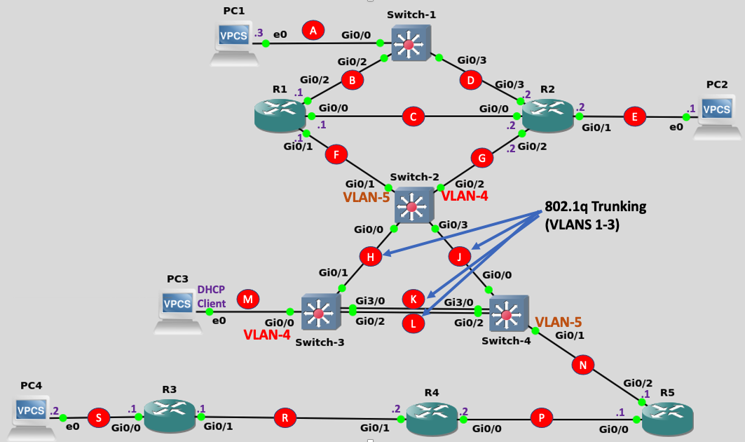
This lab will test your knowledge and skills at implementing eleven of the most important features and protocols that were covered within INE's CCNA Learning Path.
Solutions
Task-1 Solutions
Configuration to apply to all routers:
    enable
    config t
    no ip domain-lookup
    line con 0
     logging synch
     exit
    enable password cisco
    !
    interface gig0/0
      no shut
      exit
    !
    interface gig0/1
      no shut
      exit
    !
    interface gig0/2
      no shut
      exit
    !
    interface gig0/3
      no shut
      exit
    !
    hostname [device hostname]
On all switches:
    enable
    config t
    no ip domain-lookup
    line con 0
     logging synch
     exit
    enable password cisco
    !
    hostname [device hostname]
R1-specific (for Telnet)
    line vty 0 4
    password cisco
    login
    transport input telnet
R2-specific (for SSH)
    hostname R2
    ip domain-name ine.com
    crypto key generate rsa
    How many bits in the modulus [512]: 1024

    ip ssh ver 2
    username ine privilege 15 pass cisco
    line vty 0 4
    transport input ssh
    login local
    end
On all devices:
    copy running-config startup-config
    ...or...
    write memory

    show cdp neighbor
Task-2 Solutions
Switches-2, 3 and 4:
    enable
    config t
    vlan 4
     name Payroll
     exit
    vlan 5
     name Engineering
     exit
Switch-2:
    enable
    config t
    interface gig0/1
      switchport mode access
      switchport access vlan 5
      exit
    !
    interface gig0/2
      switchport mode access
      switchport access vlan 4
      exit
    !
    interface range gig0/0 , gig0/3
      switchport trunk encapsulation dot1q
      switchport mode dynamic desirable
      switchport trunk allowed vlan 1,4-5
      exit
    !
    interface gig0/3
      switchport trunk native vlan 4
    end
    wr
Switch-3:
    enable
    config t
    interface gig0/0
      switchport mode access
      switchport access vlan 4
      exit
    !
    interface range gig0/1-2 , gig3/0
      switchport trunk encapsulation dot1q
      switchport trunk allowed vlan 1,4-5
      exit
    !
    interface range gig0/2 , gig3/0
      switchport mode dynamic desirable
      exit
    !
    end
    wr
Switch-4:
    enable
    config t
    interface gig0/1
      switchport mode access
      switchport access vlan 5
      exit
    !
    interface range gig0/0, gig0/2 , gig3/0
      switchport trunk encapsulation dot1q
      switchport trunk allowed vlan 1,4-5
      exit
    !
    interface gig 0/0
     switchport trunk native vlan 4
     exit
    !
    end
    wr
Task-3 Solutions
- Starting Network: 50.50.50.0/24
| Link ID |
Qty of Hosts |
Subnet Mask |
Network/Prefix |
| A/B/D |
6 |
/29 |
50.50.50.112 |
| C |
2 |
/30 |
50.50.50.120 |
| E |
30 |
/27 |
50.50.50.64 |
| F/N |
40 |
/26 |
50.50.50.0 |
| G/M |
12 |
/28 |
50.50.50.96 |
- Starting Network 70.70.70.0/24
| Link ID |
Qty of Hosts |
Subnet Mask |
Network/Prefix |
| S |
100 |
/25 |
70.70.70.0 |
| R |
55 |
/26 |
70.70.70.128 |
| P |
22 |
/27 |
70.70.70.192 |
- R1 IPv4 Addressing Configuration
    config t
    !
    int gig 0/0
     ip address 50.50.50.121 255.255.255.252
     exit
    !
    int gig 0/1
     ip address 50.50.50.1 255.255.255.192
     exit
    !
    int gig 0/2
     ip address 50.50.50.113 255.255.255.248
     exit
    !
    end
    wr
- R2 IPv4 Addressing Configuration
    config t
    !
    int gig 0/0
     ip address 50.50.50.122 255.255.255.252
     exit
    !
    int gig 0/1
     ip address 50.50.50.65 255.255.255.224
     exit
    !
    int gig 0/2
     ip address 50.50.50.97 255.255.255.240
     exit
    !
    int gig 0/3
     ip address 50.50.50.114 255.255.255.248
     exit
    !
    end
    wr
- R5 IPv4 Addressing Configuration
    config t
    !
    int gig 0/0
     ip address 70.70.70.193 255.255.255.224
     exit
    !
    int gig 0/2
     ip address 50.50.50.2 255.255.255.192
     exit
    !
    end
    wr
- R4 IPv4 Addressing Configuration
    config t
    !
    int gig 0/0
     ip address 70.70.70.194 255.255.255.224
     exit
    !
    int gig 0/1
     ip address 70.70.70.129 255.255.255.192
     exit
    !
    end
    wr
- R3 IPv4 Addressing Configuration
    config t
    !
    int gig 0/0
     ip address 70.70.70.1 255.255.255.128
     exit
    !
    int gig 0/1
     ip address 70.70.70.130 255.255.255.192
     exit
    !
    end
    wr
Task-4 Solutions
    config t
    !
    int gig 0/2
     standby 1 ip 50.50.50.118
     standby 1 priority 101
     standby 1 preempt
     exit
    end
    wr
    config t
    !
    int gig 0/3
     standby 1 ip 50.50.50.118
     exit
    end
    wr
Task-5 Solutions
- R2 DHCP Server Configuration
    config t
    !
    ip dhcp pool PC1
      network 50.50.50.112 /29
      default-router 50.50.50.118
      lease 2 12 30
    !
    ip dhcp pool PC2
      network 50.50.50.64 /27
      default-router 50.50.50.65
      lease 2 12 30
    !
    ip dhcp pool PC3
      network 50.50.50.96 /28
      default-router 50.50.50.97
      lease 2 12 30
    !
    end
    wr
- R3 DHCP Server Configuration
    config t
    !
    ip dhcp pool PC4
      network 70.70.70.0 /25
      default-router 70.70.70.1
    !
    end
    wr
Task-6 Solutions
- Switch-2 RSTP Configuration
    config t
    spanning-tree mode rapid-pvst
    !
    spanning-tree vlan 1 root primary
    !
    interface range gig 0/1 - 2
     spanning-tree portfast edge
     exit
    !
    interface gig 0/0
     spanning-tree vlan 4 cost 100
     exit
    !
    end
    wr
- Switch-3 RSTP Configuration
    config t
    spanning-tree mode rapid-pvst
    !
    spanning-tree vlan 4 root primary
    !
    interface gig 0/0
     spanning-tree portfast edge
     exit
    !
    interface range gig 0/2 , gig 3/0
     channel-group 1 mode active
    !
    end
    wr
- Switch-4 RSTP Configuration
    config t
    spanning-tree mode rapid-pvst
    !
    spanning-tree vlan 5 root primary
    !
    interface gig 0/1
     spanning-tree portfast edge
     exit
    !
    interface range gig 0/2 , gig 3/0
     channel-group 1 mode passive
    !
    end
    wr
Task-7 Solutions
- R3 IPv4 Static Route Configuration
    config t
    !
    ip route 0.0.0.0 0.0.0.0 70.70.70.129
    end
    wr
- R4 IPv4 Static Route Configuration
    config t
    !
    ip route 0.0.0.0 0.0.0.0 70.70.70.193
    ip route 70.70.70.0 255.255.255.128 70.70.70.130
    !
    end
    wr
- R5 IPv4 Static Route Configuration
    config t
    !
    ip route 70.0.0.0 255.0.0.0 70.70.70.194
    !
    end
    wr
Task-8 Solutions
    config t
    !
    router ospf 1
     router-id 0.0.0.1
     exit
    !
    interface range gig 0/0, gig 0/2
      ip ospf 1 area 0
      exit
    !
    interface gig0/1
     ip ospf 1 area 1
     exit
    !
    end
    wr
    config t
    !
    router ospf 1
     router-id 0.0.0.2
     exit
    !
    interface range gig 0/0-1, gig 0/3
      ip ospf 1 area 0
      exit
    !
    interface gig0/2
     ip ospf 1 area 1
     exit
    !
    end
    wr
    config t
    !
    router ospf 1
     router-id 0.0.0.5
     default-information originate always
     exit
    !
    interface gig0/2
     ip ospf 1 area 1
     exit
    !
    end
    wr
Task-9 Solutions
    config t
    !
    interface loopback0
     ip address 22.22.22.1 255.255.255.240
     ip ospf network point-to-point
     exit
    !
    router ospf 1
     network 22.22.22.0 0.0.0.255 area 0
     exit
    !
    access-list 1 permit host 50.50.50.66
    !
    ip nat pool Final-Lab 22.22.22.2 22.22.22.14 netmask     255.255.255.240
    ip nat inside source list 1 pool Final-Lab
    !
    interface gig 0/1
     ip nat inside
     exit
    !
    interface range gig 0/0 , gig 0/3
     ip nat outside
     exit
    !
    end
    wr
Note: Viewing the IP routing table within R2 shows that to reach Subnet-S, R2 would need to use the OSPF default route that it has learned. And this default route shows two, equal cost paths...one through Gig0/0 and another through Gig0/3. So because you don't know which path will be selected when PC2 sends packets to PC4 you should make both of them NAT Outside interfaces.
    R2#sho ip route
    [SNIP]

    O*E2  0.0.0.0/0 [110/1] via 50.50.50.121, 01:01:57,     GigabitEthernet0/0
                    [110/1] via 50.50.50.113, 01:01:57,     GigabitEthernet0/3
          50.0.0.0/8 is variably subnetted, 9 subnets, 6 masks
    [SNIP]
Task-10 Solutions
Step-1 of Task-10 is assigning relevant IPv6 addresses to interfaces
- R4 IPv6 Interface Configuration
    conf t
    ipv6 unicast-routing
    !
    interface gig0/1
     ipv6 address 2001:aaaa:bbbb:cc0b::/64 eui-64
     exit
    !
    interface gig0/0
     ipv6 address 2001:aaaa:bbbb:cc27::/64 eui-64
     exit
    !
    end
    wr
- R3 IPv6 Interface Configuration
    conf t
    ipv6 unicast-routing
    !
    interface gig0/0
     ipv6 address 2001:aaaa:bbbb:cc04::3/64
     exit
    !
    interface gig0/1
     ipv6 address 2001:aaaa:bbbb:cc0b::3/64
     exit
    !
    end
    wr
- R5 IPv6 Interface Configuration
    conf t
    ipv6 unicast-routing
    !
    interface gig0/0
     ipv6 address autoconfig
     exit
    !
    interface loopback1
     ipv6 address 2001:5555:5555::5/64
     exit
    !
    end
    wr
Step-2 for Task-10 is determining the interface-IDs for router interfaces that obtained dynamic addresses. This will be needed for our IPv6 static routes later.
    Router-5#show ipv6 interface brief
    GigabitEthernet0/0     [up/up]
        FE80::E68:6BFF:FE6A:0
        2001:AAAA:BBBB:CC27:E68:6BFF:FE6A:0
    Router-4#show ipv6 interface brief
    GigabitEthernet0/0     [up/up]
        FE80::E04:78FF:FE85:0
        2001:AAAA:BBBB:CC27:E04:78FF:FE85:0
    GigabitEthernet0/1     [up/up]
        FE80::E04:78FF:FE85:1
        2001:AAAA:BBBB:CC0B:E04:78FF:FE85:1
Step-3 for Task-10 is configuring the IPv6 Static Routes
    config t
    !
    ipv6 route ::/0 2001:AAAA:BBBB:CC0B:E04:78FF:FE85:1
    end
    wr
    config t
    !
    ipv6 route 2001:aaaa:bbbb:cc04::/64 2001:aaaa:bbbb:cc0b::3
    ipv6 route 2001:5555:5555::/64 2001:AAAA:BBBB:CC27:E68:6BFF:FE6A:0
    end
    wr
    config t
    !
    ipv6 route ::/0 2001:AAAA:BBBB:CC27:E04:78FF:FE85:0
    !
    end
    wr
Task-11 Solutions
All of the tasks in this ACL section could be accomplished by configuring and applying them to routers R1 and R2.
Because (in your verification steps) it was inferred that neither R1 nor R2 should be allowed to ping PC1 (yet they are in the same subnet as PC1) the only way to accomplish the first ACL requirement of restricting pings would be to apply an ACL "inbound" on Gig0/2 of R1 and Gig0/3 of R2:
In the solutions below, PC1 was given the DHCP address of 50.50.50.115. Your lab may be different.
    config t
    !
    access-list 101 permit icmp host 50.50.50.115 70.70.70.128 0.0.0.127
    access-list 101 deny icmp host 50.50.50.115 any
    access-list 101 permit ip any any
    !
    access-list 2 deny 70.70.70.1
    access-list 2 deny 70.70.70.130
    access-list 2 permit any
    !
    interface gig0/2
     ip access-group 101 in
     exit
    !
    line vty 0 4
     access-class 2 in
     exit
    end

    wr
    config t
    !
    access-list 101 permit icmp host 50.50.50.115 70.70.70.128 0.0.0.127
    access-list 101 deny icmp host 50.50.50.115 any
    access-list 101 permit ip any any
    !
    access-list 2 deny 70.70.70.194
    access-list 2 deny 70.70.70.129
    access-list 2 permit any
    !
    interface gig0/3
     ip access-group 101 in
     exit
    !
    line vty 0 4
     access-class 2 in
     exit
    end
    wr