NOTE: Please read the following lab guidelines before working on this lab. - If any device contains preconfigured login credentials use, cisco/cisco - If you plan working on more than one Lab Task during the day (all related to the same course), open the first lab environment and keep it open for subsequent labs (unless instructed otherwise) to save yourself excessive bootup time. Simply read the Lab Objectives from subsequent labs and perform them on your first, opened lab environment.
Solutions:
Task-1 Solution
Erasing the startup configuration files
Switch-2#erase startup-config
Erasing the nvram filesystem will remove all configuration files! Continue? [confirm]
[OK]
Erase of nvram: complete
Switch-2#
Erasing the VLAN.dat file
NOTE: On a real Cisco switch, the VLAN.dat file would also need to be deleted (which is stored in "flash:" memory). If you don't delete this file, your non-default VLANs will persist after a reload. However, because the switches in this lab environment are emulated, their VLAN.dat file is stored in NVRAM. Hopefully you discovered this for yourself using the command, "dir all" to search for the location of this file.
Here we see that attempting to delete the vlan.dat file from its normal location fails:
Switch-2#delete flash:vlan.dat
Delete filename [vlan.dat]?
Delete flash0:/vlan.dat? [confirm]
%Error deleting flash0:/vlan.dat (File not found)
Switch-2#dir all
Directory of flash0:/
1  drw-           0  Jan 30 2013 00:00:00 +00:00  boot


264  drw-           0  Oct 14 2013 00:00:00 +00:00  config
[Output Omitted For Brevity]
No space information available
Directory of nvram:/
254  -rw-           0                      startup-config
  255  ----           0                      private-config
    1  ----          31                      udi
    2  ----          35                      persistent-data
    3  -rw-         736                      vlan.dat  <-----
    4  -rw-           0                      ifIndex-table
Switch-2#delete nvram:vlan.dat
Delete filename [vlan.dat]?
Delete nvram:vlan.dat? [confirm]
Switch-2#
Switch-2#reload
Proceed with reload? [confirm]
*Jun 29 13:59:42.708: %SYS-5-RELOAD: Reload requested by console. Reload Reason: Reload command.
 *Jun 29 13:59:45.728
Verification of success:
Switch>  <-----Hostname is back to the default name for a Cisco switch
Switch>enable
Switch#show vlan
VLAN Name                             Status    Ports

1    default                          active    Gi0/0, Gi0/1, Gi0/2, Gi0/3
                                                Gi1/0, Gi1/1, Gi1/2, Gi1/3
                                                Gi2/0, Gi2/1, Gi2/2, Gi2/3
                                                Gi3/0, Gi3/1, Gi3/2, Gi3/3
1002 fddi-default                     act/unsup
VLANs 2-4 are now gone.
Task-2 Solution
Change Switch-2's hostname to "Switch-2"
Switch>
Switch>enable
Switch#conf t
Enter configuration commands, one per line.  End with CNTL/Z.
Switch(config)#hostname Switch-2
Switch-2(config)#end
Switch-2#
Use a single command to administratively disable ports Gig2/0 through Gig3/3
Switch-2#config t
Enter configuration commands, one per line.  End with CNTL/Z.
Switch-2(config)#interface range gig 2/0 - 3 , gig 3/0 - 3
Switch-2(config-if-range)#shutdown
Switch-2(config-if-range)#end
Switch-2#
*Jun 29 14:24:56.352: %SYS-5-CONFIG_I: Configured from console by console
*Jun 29 14:24:57.028: %LINK-5-CHANGED: Interface GigabitEthernet2/0, changed state to administratively down
Apply a comment within Gig0/1 that reads, "Connected to Switch-1"
Switch-2#
Switch-2#config t
Enter configuration commands, one per line.  End with CNTL/Z.
Switch-2(config)#interface gig 0/1
Switch-2(config-if)#description Connected to Switch-1
Switch-2(config-if)#end
Switch-2#
Switch-2#
*Jun 29 14:25:43.403: %SYS-5-CONFIG_I: Configured from console by console
Switch-2#show run interface gig 0/1
Building configuration...
Current configuration : 89 bytes
!
interface GigabitEthernet0/1
 description Connected to Switch-1
 negotiation auto
end
Apply a management IPv4 address of 10.0.0.22/26 that will be reachable by all hosts in VLAN-1
Switch-2#conf t
Enter configuration commands, one per line.  End with CNTL/Z.
Switch-2(config)#interface vlan 1
Switch-2(config-if)#ip address 10.0.0.22 255.255.255.192
Switch-2(config-if)#no shutdown
Switch-2(config-if)#end
Switch-2#
*Jun 29 14:27:13.256: %SYS-5-CONFIG_I: Configured from console by console
Switch-2#
*Jun 29 14:27:14.233: %LINK-3-UPDOWN: Interface Vlan1, changed state to up
*Jun 29 14:27:15.233: %LINEPROTO-5-UPDOWN: Line protocol on Interface Vlan1, changed state to up
Switch-2#
Login to PC-1 and ping the management IPv4 address of Switch-2
PC1> ping 10.0.0.22
84 bytes from 10.0.0.22 icmp_seq=1 ttl=255 time=1.855 ms
84 bytes from 10.0.0.22 icmp_seq=2 ttl=255 time=1.524 ms
84 bytes from 10.0.0.22 icmp_seq=3 ttl=255 time=1.478 ms
The command that meets the criteria for viewing the interface status is "show interfaces status"
Switch-2#show interfaces status
Port      Name               Status       Vlan       Duplex  Speed Type
Gi0/0                        connected    1          a-full   auto RJ45
Gi0/1     Connected to Switc connected    1          a-full   auto RJ45
Gi0/2                        connected    1          a-full   auto RJ45
Gi0/3                        notconnect   1          a-full   auto RJ45
Gi1/0                        notconnect   1          a-full   auto RJ45
Gi1/1                        notconnect   1          a-full   auto RJ45
Gi1/2                        notconnect   1          a-full   auto RJ45
Gi1/3                        notconnect   1          a-full   auto RJ45
Gi2/0                        disabled     1            auto   auto RJ45
Gi2/1                        disabled     1            auto   auto RJ45
Gi2/2                        disabled     1            auto   auto RJ45
Gi2/3                        disabled     1            auto   auto RJ45
Gi3/0                        disabled     1            auto   auto RJ45
Gi3/1                        disabled     1            auto   auto RJ45
Gi3/2                        disabled     1            auto   auto RJ45
Gi3/3                        disabled     1            auto   auto RJ45
Task-3 Solutions
Pinging from PC-1 to 10.0.0.22
PC1> ping 10.0.0.22
84 bytes from 10.0.0.22 icmp_seq=1 ttl=255 time=1.415 ms
84 bytes from 10.0.0.22 icmp_seq=2 ttl=255 time=1.528 ms
84 bytes from 10.0.0.22 icmp_seq=3 ttl=255 time=1.494 ms
84 bytes from 10.0.0.22 icmp_seq=4 ttl=255 time=1.455 ms
84 bytes from 10.0.0.22 icmp_seq=5 ttl=255 time=1.408 ms
PC1>
Discerning the MAC address of PC-1 by viewing output from Switch-2:
Switch-2#show mac address-table dynamic interface gig0/0
          Mac Address Table

Vlan    Mac Address       Type        Ports
----    -----------       --------    -----
   1    0050.7966.6800    DYNAMIC     Gi0/0
Total Mac Addresses for this criterion: 1
Switch-2#
Confirming an IP address on router R1:
Router#show ip interface brief
Interface IP-Address OK? Method Status Protocol
GigabitEthernet0/0 unassigned YES NVRAM administratively down down
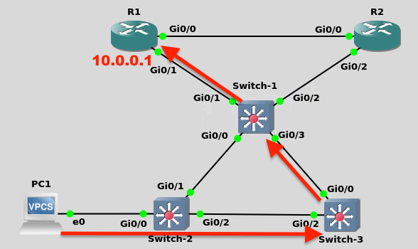
GigabitEthernet0/1 10.0.0.1 YES NVRAM up up Once you learned the MAC address of PC-1 (in Task-3: Step-2) you can now view the MAC Address-tables of all three switches and identify which ports learned of this MAC. The ports upon which this MAC was learned are the ONLY ports that will receive frames from this source MAC, and transmit frames BACK to this source MAC.
In my topology, PC-1's MAC address was 0050.7966.6800:
Switch-2#show mac address-table dynamic interface gig0/0
          Mac Address Table

Vlan    Mac Address       Type        Ports
----    -----------       --------    -----
   1    0050.7966.6800    DYNAMIC     Gi0/0
Switch-1 learned of this MAC on port Gig0/3:
Switch-1#show mac address-table address 0050.7966.6800
          Mac Address Table

Vlan    Mac Address       Type        Ports
----    -----------       --------    -----
   1    0050.7966.6800    DYNAMIC     Gi0/3
Switch-3 learned of this MAC on port Gig0/2:
Switch-3#show mac address-table address 0050.7966.6800
          Mac Address Table

Vlan    Mac Address       Type        Ports
----    -----------       --------    -----
   1    0050.7966.6800    DYNAMIC     Gi0/2
Total Mac Addresses for this criterion: 1
Switch-3#
So the path through the switched network for frames to/from PC-1 and R1 was as follows: